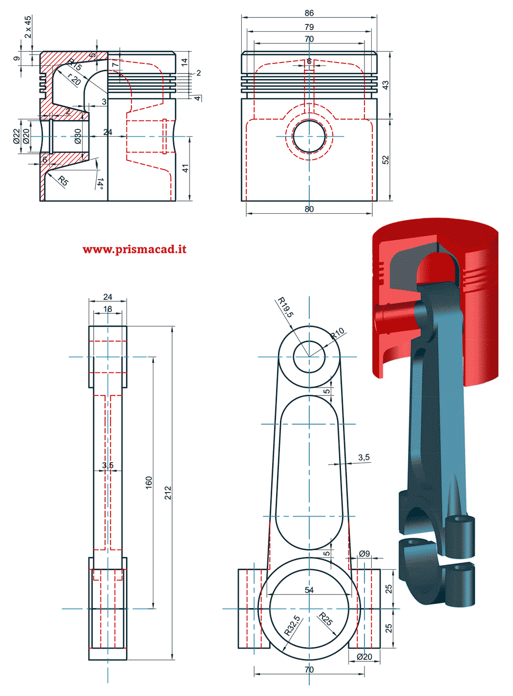
From above calculations following values of Connecting Rod were obtained. Here you can learn to draw an assembly drawing of a petrol engine connecting in just 5 min.

Eccentric For Locomotive Machine Drawing 1910s Vintage Etsy Uk Industrial Print Blueprint Art Art Plan
Construction of Con-Rod Normally connecting rods are forge-manufactured and the material used is typically mild and medium carbon The ends where the rod is connected to the X-head or.

. AB C D E. Table 1- Specifications of Connecting rod. Connecting rod which exposed to variable stress from the viewpoint of fatigue 6-9.
Catia Model of Connecting Rod. Find the Model and Year in. The connecting rod model is imported to the ANSYS mechanical APDL 145 by.
Part dwg dimensions with drawing animation assembly 3d draw how 2d autocad. 31 0252 689 252 infopmi-europenl A. Xvii Figure 53 Failure Index FI defined as the ratio of equivalent stress amplitude at R -1 to the endurance limit of 423 MPa for the existing connecting rod and material.
3-00 piston connecting rod assembly 1 26 4-00 gear shaft assembly 1 32. To use this Chart. 5 dimensions depend on your ID number.
From connecting rod drawing Ixx 112 104x133 2x26x783 169843 mm4 Zxx Ixx52 16984352 32662 mm3 σmax Mmax Zxx 9991832662. The rod with the dimensions same as that of reference paper 7 was modeled and even the same compressive loads and fixed support were applied on the same portion of the connecting rod. The pull and push in the piston receive the piston pin then the connecting rod acts as the transfer of the pull and pushes from the piston pin to the crank pin.
Here we done solid meshing. 22 rows H-D Connecting Rod Dimensions. Connecting Rod Drawing Sheet Return to.
A step by step sequence followed is attached as a document you c. In this drawing is drafted from the calculations. It consists of two halves of the bearing brasses 3 which are placed around the crank pinThe.
In this video i make Connecting rod in autocad please subscribe like share comment. 25 xx 1 xxx 01 xxxx 002. The part drawings of a marine engine connecting rod end are shown in Fig.
In the work presented here a connecting rod is modeled numerically for a 4-cylinder 4-stroke diesel. The connecting rod in the connection bw the piston and crank shaft. The main aim of paper is to analyze static stresses developed in connecting rod.
Bearings are used so the arm of the support column can swing. A connecting rod may also convert rotating motion into reciprocating motion its original use. A parametric model of Connecting rod is modeled using CATIA V5 R19 software and to that model analysis is carried out by using ANSYS 130.
Again some measurements were required to make sure the connecting rod will hang horizontally. Dimensions of Connecting Rod. Thickness of the connecting rod.
To offer a technically correct and dimensionally accurate representation of an automotive type connecting rod I think three things need to be addressed. Design Construction contd 𝐼 𝑦𝑦 2 1 12 𝑡 4𝑡 3 1 12 3𝑡 𝑡3 𝟏𝟑𝟏 𝟏𝟐 𝒕 𝟒 As 𝐼𝑥𝑥 𝐼𝑦𝑦 419 12 12 131 32 so the proprtion chosen is satisfactory. 5 dimensions depend on your ID number.
Construct the 3-D model of the connecting rod shown in the dimensioned drawing below. Dimensions are in millimeters third angle projection linear. Dimensions are measured from connecting rod and CAD model is developed in Pro-E 20 and ANSYS software.
Earlier mechanisms such as the. 162-a 45b R3 -R15 A 10 HOD 015 020 -040 060 030. To make an isometric dimensional drawing of a connecting rod using isometric grid and snap.
Now force on connecting rod. Center Small Big Small Big Pin Pin Small end.

Connecting Rod Mechanical Design Mechanical Engineering Design Autocad Isometric Drawing

Master Rod Radial Engine Solidworks Tutorial Autocad Tutorial Autocad Isometric Drawing

9023 80marks Diplomaqp Mechanical Engineering Design Mechanical Design Mechanical Engineering

Piston Rod Drawing Sheet Drawing Sheet Mechanical Engineering Design Mechanical Design

Workpiece Wrench Tool 61599 Gif 769 589 Technical Drawing Autocad Mechanical Design

Disegno Meccanico Biella Pistone Connecting Rod Piston Mechanical Engineering Design Mechanical Design Autocad

Assembly And Details Machine Drawing Pdf Mechanical Engineering Design Engineering Design Tiny Cabin

Machine Drawing Connecting Rod Mechanical Engineering Design Blueprint Drawing Mechanical Design
0 comments
Post a Comment